|
A fundamentally new non-rocket geocosmic circular transport system (GCTS) is proposed to solve a very complex problem of reducing the cost of geocosmic transportation by about a thousand times. It will function as an energy hyperstorage unit.
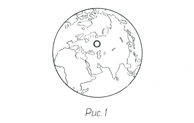
GCTS is a circular structure with the ring diameter of about 100 km (see Fig. 1) located underground
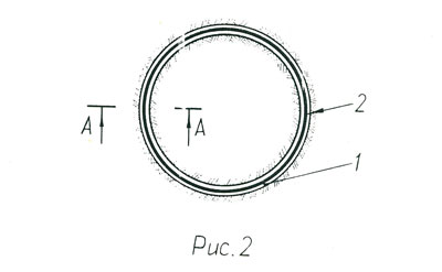
at a depth of 100-3,000 meters in the zone of maximal energy consumption, for example, around Moscow. Fig. 2 shows
GCTS in cross-section, top view. It is a vacuum circular channel 1 with the cross-sectional diameter of 300-500
mm, in which a circular rotor 2 with the cross-sectional diameter of 100-300 mm is installed.
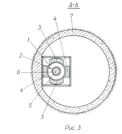
In cross section GCTS (see Fig. 3) is a tubular vacuum channel 1, which wall is produced of
dia- or paragnetic material, for example, of non-conductive composite material based on a polymer, which freely
insures passage of a magnetic field from double-sided linear induction motor 3 and system 4 of the
magnetic suspension of rotor 2 arranged along the channel. The rotor consists of core 5 and the applied
layer 6 made of a high-electroconductive material. GCTS is located in tunnel 7 with a diameter of 2-3 m
required for staff and equipment accommodation.
GCTS operation as an accumulating power plant is the following: after switching on system 4 of
magnetic suspension (Fig. 3) the rotor suspends without touching the walls of channel 1, and alternating
electric current is applied to the stator coils of linear motor 3, resulting in appearance of a magnetic field
running along the rotor in the gap between the lower and upper stator coils formed by multi-phase currents of the
stator coils.
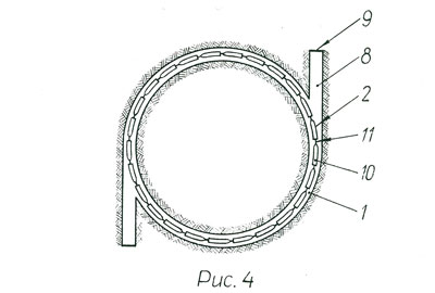
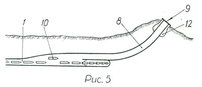
GCTS operation as a means of delivering payload into space is as follows: for this purpose GCTS has
from one to several dozen (depending on the plane of the orbit for delivering payload into space) branch channels 8
(see Fig. 4) equally arranged along the entire length of the ring. The outlet channel porthole is closed with a
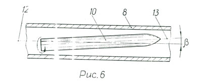
membrane (or a vacuum gate valve) 9 and rotor 2 is located in the circular channel. The rotor is
composed of separate shells 10 along the length, each 1-10 meters long depending on the functions performed.
The shells are connected with each other in a continuous ring with special docking units 11.
Fig. 5 shows branch channel 8 in the longitudinal section at the moment, when one of the shells
10 enters it from the main circular channel 1.
For more details see the brochure
"Minor and major physical models of the General Planetary Vehicles as circular energy hyperstorage units" (in Russian) with the following content:
- Introduction
- GCTS design used as an accumulating power plant
- GCTS operation as an accumulating power plant
- Feasibility study of GCTS used as an accumulating power plant:
- capital cost,
- linear electric motor and magnetic suspension,
- requirements to materials,
- timing of development and implementation.
- GCTS operation as a means of delivering payload into space
- The main technical and economic indicators of GCTS used as a means of delivering payload into space
- Comparison of GCTS with other geocosmic transport systems
- Minor and major physical models of the General Planetary Vehicle as a circular energy hyperstorage unit
- Literature
- Illustration figures
|